MATEK - Flight Controller F405 WMN
F405-WMN Quick Start Guide PDF
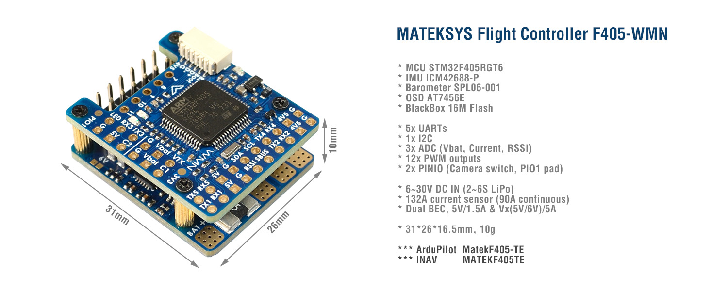
FC Specifications
MCU: STM32F405RGT6, 168MHz , 1MB Flash
IMU: ICM42688-P
Baro: SPL06-001
OSD: AT7456E
Blackbox: 16M Flash
5x UARTs, 1x Softserial_Tx option(INAV)
12x PWM outputs
1x I2C
3x ADC (VBAT, Current, RSSI)
1x spare PINIO
USB/Beep Extender with Type-C(USB2.0)
Built in inverter on UART2-RX for SBUS input
Switchable Dual Camera Inputs
Power
6~30V DC IN (2~6S LiPo)
132A Current Sense (INAV Scale 250, ArduPilot 40A/V)
PDB/Current sense resistor: 90A continuous, 132A burst.
BEC 5V 1.5A for FC & Peripherals
BEC Vx 5A for servos, 5V/ 6V option
Vbat for VTX and camera
LDO 3.3V 200mA
Battery Voltage Sensor: 1k:20k
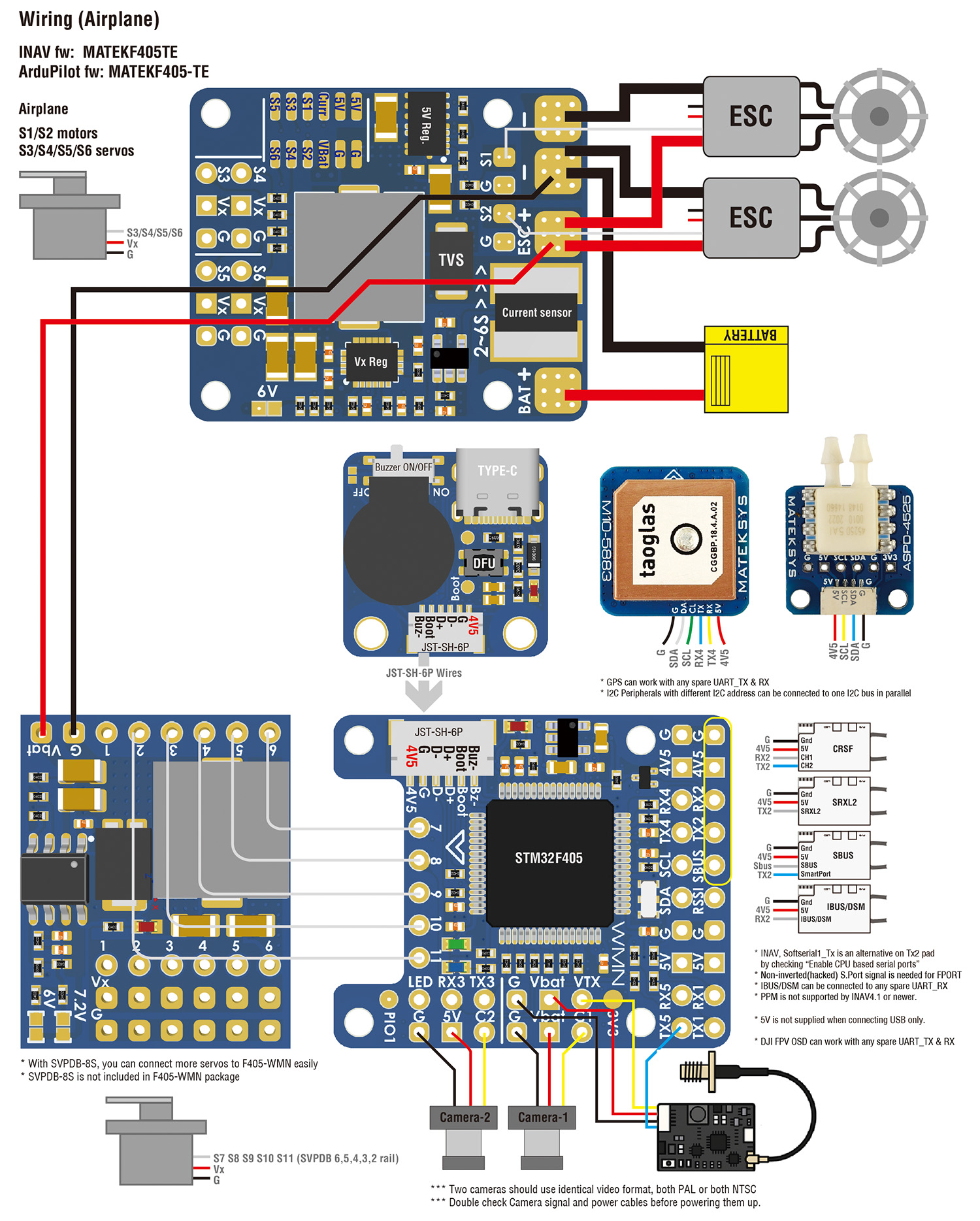
FC Firmware
ArduPilot: MatekF405-TE
INAV: MATEKF405TE (INAV 5.0 or newer)
Physical
Dimensions: 31 x 26 x 16.5 mm
Mounting: 22 x 22mm, Φ2mm
Weight: 10g
Including
1x F405-WMN
1x USB(Type-C)/Beep (Passive buzzer) Extender + 20cm JST-SH-6P to JST-SH-6P cable for USB extender.
Dupont 2.54 pins (Board is shipped unsoldered)
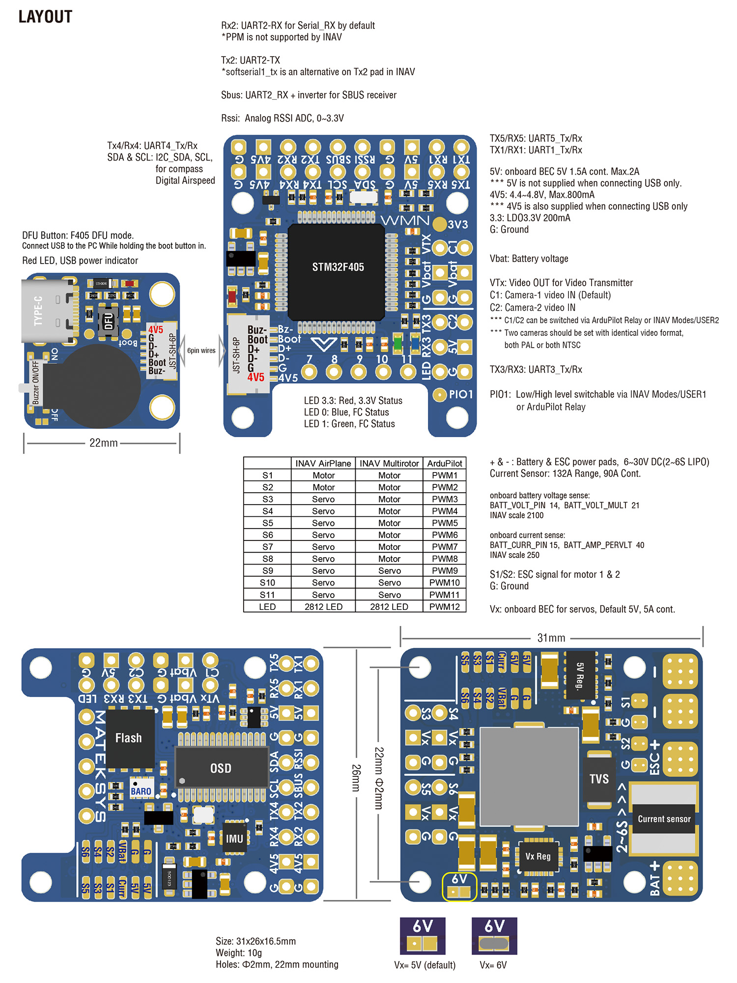
INAV Mapping
| INAV MultiRotor | INAV Plane | ||||
| PWM | S1 | 5 V tolerant I/O | TIM8_CH4 | Motor | Motor |
| S2 | 5 V tolerant I/O | TIM8_CH3 | Motor | Motor | |
| S3 | 5 V tolerant I/O | TIM1_CH3N | Motor | Servo | |
| S4 | 5 V tolerant I/O | TIM1_CH1 | Motor | Servo | |
| S5 | 5 V tolerant I/O | TIM2_CH4 | Motor | Servo | |
| S6 | 5 V tolerant I/O | TIM2_CH3 | Motor | Servo | |
| S7 | 5 V tolerant I/O | TIM2_CH2 | Motor | Servo | |
| S8 | 5 V tolerant I/O | TIM2_CH1 | Motor | Servo | |
| S9 | 5 V tolerant I/O | TIM12_CH1 | Servo | Servo | |
| S10 | 5 V tolerant I/O | TIM13_CH1 | Servo | Servo | |
| S11 | 5 V tolerant I/O | TIM4_CH1 | Servo | Servo | |
| LED | 5 V tolerant I/O | TIM3_CH4 | 2812LED | 2812LED | |
| ADC | Vbat Pad | 1K:20K divider builtin 0~30V |
Vbat ADC ADC_CHANNEL_1 |
INAV voltage scale 2100 | |
| Curr pad | 0~3.3V | Current ADC ADC_CHANNEL_2 |
scale 250 | ||
| RSSI Pad | 0~3.3V | RSSI ADC ADC_CHANNEL_3 |
Analog RSSI | ||
| No Pad | AirS ADC ADC_CHANNEL_4 |
||||
| I2C | I2C1 | 5V tolerant I/O | Compass | QMC5883 / HMC5883 /MAG3110 / LIS3MDL | |
| OLED | 0.96″ | ||||
| onboard Barometer | SPL06-001 | ||||
| Digital Airspeed sensor | MS4525 | ||||
| Temperature sensor | |||||
| UART 5V tolerant I/O |
USB | USB | |||
| TX1 RX1 | 5V tolerant I/O | UART1 | USER | ||
| TX3 RX3 | UART3 | USER | |||
| TX4 RX4 | UART4 | USER | |||
| TX5 RX5 | UART5 | USER | |||
| No Pad | UART6 | – | |||
| TX2 RX2 SBUS |
5V tolerant I/O | UART2 | RC input/Receiver | ||
| Sbus pad | for SBUS receiver, Sbus pad = RX2+inverter | ||||
| RX2 pad | IBUS/DSM/PPM | ||||
| TX2 & RX2 | CRSF | ||||
| TX2 pad | SmartPort Telemetry | enable Softserial_Tx1 | |||
| TX2 pad | FPORT, uninverted S.Port/F.Port signal (hacked) | ||||
| TX2 pad | SRXL2 | ||||
PINIO
PINIO1 /PIO1 pad, Low Level by default, Low/High level switchable by Mode-USER1
PINIO2 is for camera input switch by Modes-USER2
Tips
- F405-WMN has INAV fw preloaded for QC
- Download INAV firmware 4.1.x from our website. Target MATEKF405TE is not listed in INAV configurator 4.x.x,
- You may download INAV fw 5.0 or newer directly from INAV configurator 5.x or newer.
ARDUPILOT
| ArduPilot | |||||
| PWM 5V tolerant I/O |
S1 | PWM1 GPIO50 | TIM8_CH4 | DMA/DShot | Group1 |
| S2 | PWM2 GPIO51 | TIM8_CH3 | DMA/DShot | ||
| S3 | PWM3 GPIO52 | TIM1_CH3N | DMA/DShot | Group2 | |
| S4 | PWM4 GPIO53 | TIM1_CH1 | DMA/DShot | ||
| S5 | PWM5 GPIO54 | TIM2_CH4 | DMA/DShot | Gourp3 | |
| S6 | PWM6 GPIO55 | TIM2_CH3 | DMA/DShot | ||
| S7 | PWM7 GPIO56 | TIM2_CH2 | DMA/DShot | ||
| S8 | PWM8 GPIO57 | TIM2_CH1 | DMA/DShot | ||
| S9 | PWM9 GPIO58 | TIM12_CH1 | NO DMA | Gourp4 | |
| S10 | PWM10 GPIO59 | TIM13_CH1 | NO DMA | Gourp5 | |
| S11 | PWM11 GPIO60 | TIM4_CH1 | NO DMA | Gourp6 | |
| LED pad | PWM12 GPIO61 | TIM3_CH4 | DMA/DShot | Gourp7 | |
| SERVO12_FUNCTION 120, NTF_LED_TYPES neopixel | |||||
| Mixing Dshot and normal PWM operation for outputs is restricted into groups, ie. enabling Dshot for an output in a group requires that ALL outputs in that group be configured and used as Dshot, rather than PWM outputs. If servo and motor are mixed in same group, make sure this group run lowest PWM frequency according to the servo specification. ie. Servo supports Max. 50Hz, ESC must run at 50Hz in this group. |
|||||
| ADC | Vbat Pad | 1K:20K divider builtin 0~30V |
Vbat ADC
onboard battery voltage |
BATT_VOLT_PIN BATT_VOLT_MULT |
14 21.0 |
| Curr pad | 0~3.3V | current sensor ADC
onboard current sense |
BATT_CURR_PIN BATT_AMP_PERVLT |
15 40 |
|
| RSSI Pad | 0~3.3V | RSSI ADC Analog RSSI |
RSSI_ANA_PIN RSSI_TYPE |
8 2 |
|
| – | – | – | – | – | |
| I2C | I2C1 | 5V tolerant I/O | Compass | COMPASS_AUTODEC | 1 |
| onboard Baro SPL06-001 | Address | 0x76 | |||
| Digital Airspeed I2C MS4525 DLVR-L10D |
ARSPD_BUS ARSPD_TYPE ARSPD_TYPE |
1 1 9 |
|||
| UART 5V tolerant I/O |
USB | USB | console | SERIAL0 | |
| TX1 RX1 | USART1 | with DMA | telem1 | SERIAL1 | |
| TX3 RX3 | USART3 | NO DMA | telem2 | SERIAL2 | |
| TX5 RX5 | UART5 | NO DMA | GPS1 *** | SERIAL3 | |
| TX4 RX4 | UART4 | NO DMA | GPS2 *** | SERIAL4 | |
| – | – | – | – | SERIAL5 | |
| TX2 RX2 SBUS |
USART2 | with DMA | RC input/Receiver | SERIAL6 | |
| RX2 | IBUS/DSM/PPM | BRD_ALT_CONFIG 0 Default |
|||
| Sbus pad | SBUS | ||||
| TX2 & RX2 | CRSF | BRD_ALT_CONFIG 1 SERIAL6_PROTOCOL 23 |
SERIAL6_OPTIONS 0 | ||
| TX2 | uninverted FPort (hacked) | SERIAL6_OPTIONS 4 | |||
| TX2 | SRXL2 | SERIAL6_OPTIONS 4 | |||
*** If connecting just one GPS to UART4(TX4/RX4), pls set UART5 SERIAL3_PROTOCOL = -1 or non “5”. otherwise ArduPilot will stop searching for GPS during bootup if not found on the first port(SERIAL3, UART5) configured for GPS protocol.
If sending highspeed serial data (eg. 921600 baud) to the board, use USART1(Serial1) or USART2(Serial6).
Frsky Smartport Telemetry
non-inverted (hacked) S.Port signal
any spare Uart_TX
SERIALx_BAUD 57
SERIALx_OPTIONS 7
SERIALx_PROTOCOL 4 or 10(for yaapu)
DJI FPV OSD (ArduPilot 4.1)
https://ardupilot.org/plane/docs/common-msp-osd-overview.html
OSD_TYPE = 3
SERIALx_PROTOCOL = 33
MSP_OPTIONS = 0 (polling mode)
Relay(PINIO)
PINIO1, PIO1 pad, Low Level by default
PINIO2, Camera switch, C1 ON by default
# GPIOs
PA4 PINIO1 OUTPUT GPIO(81) LOW //PIO1 pad
PB5 PINIO2 OUTPUT GPIO(82) LOW //camera switch
# RCx_OPTION: RC input option
28 Relay On/Off
34 Relay2 On/Off
35 Relay3 On/Off
36 Relay4 On/Off
e.g.
RELAY1_FUNCTION 1
RELAY_PIN 81 //PIO1 GPIO
RC7_OPTION 28 //Relay On/Off, Use CH7 of Transmitter to control PIO1 Low/High Level
RELAY2_FUNCTION 1
RELAY_PIN2 82 //Camera switch GPIO
RC8_OPTION 34 //Relay2 On/Off, Use CH8 of Transmitter to control high/low level on PB5 pad
The configured feature will be triggered when the auxiliary switch’s pwm value becomes higher than 1800. It will be deactivated when the value falls below 1200.
Check the pwm value sent from the transmitter when the switch is high and low using the Mission Planner’s Initial Setup >> Mandatory Hardware >> Radio Calibration screen. If it does not climb higher than 1800 or lower than 1200, it is best to adjust the servo end points in the transmitter.
Returns Policy
You may return most new, unopened items within 30 days of delivery for a full refund. We'll also pay the return shipping costs if the return is a result of our error (you received an incorrect or defective item, etc.).
You should expect to receive your refund within four weeks of giving your package to the return shipper, however, in many cases you will receive a refund more quickly. This time period includes the transit time for us to receive your return from the shipper (5 to 10 business days), the time it takes us to process your return once we receive it (3 to 5 business days), and the time it takes your bank to process our refund request (5 to 10 business days).
If you need to return an item, simply login to your account, view the order using the "Complete Orders" link under the My Account menu and click the Return Item(s) button. We'll notify you via e-mail of your refund once we've received and processed the returned item.
Shipping
We can ship to virtually any address in the world. Note that there are restrictions on some products, and some products cannot be shipped to international destinations.
When you place an order, we will estimate shipping and delivery dates for you based on the availability of your items and the shipping options you choose. Depending on the shipping provider you choose, shipping date estimates may appear on the shipping quotes page.
Please also note that the shipping rates for many items we sell are weight-based. The weight of any such item can be found on its detail page. To reflect the policies of the shipping companies we use, all weights will be rounded up to the next full pound.
Related Products

Matek
MATEK - Flight Controller F405-WTE
FC Specifications MCU: STM32F405RGT6, 168MHz , 1MB FlashIMU: ICM42688-PBaro: SPL06-001OSD: AT7456EBlackbox: MicroSD card slotESP WiFi Telemetry(MAVLink, 14dBm)ExpressLRS 2.4G receiver(CRSF protocol,...

Matek
MATEK - Flight Controller F405 WING V2
FC Specifications MCU: STM32F405RGT6, 168MHz , 1MB FlashIMU: ICM42688-PBaro: DPS310OSD: AT7456EBlackbox: MicroSD card slot6x UARTs, 1x Softserial_Tx option(INAV)10x PWM outputs2x I2C3x ADC (VBAT,...

Matek
MATEK - Flight Controller F411-WTE
Since Mar.2023, the IMU BMI270 has been replaced with ICM42688P. Pls check out the label on the plastic bag. ICM42688P version is supported by INAV 6.0 or newer. If you stick with old firmware...

Matek
MATEK - Flight Controller H743-WING V3
FC Specifications MCU: STM32H743VIT6, 480MHz , 1MB RAM, 2MB Flash IMU: ICM42688-P(V3)+ICM42605 Baro: Infineon DPS310 (I2C2) OSD: AT7456E (SPI2) Blackbox: MicroSD card slot (SDIO) 7x Uarts...

Matek
MATEK - FLIGHT CONTROLLER H743-MINI V3
FC Specifications MCU: STM32H743VIT6, 480MHz , 1MB RAM, 2MB Flash Board V3 IMU: ICM42688-P (SPI1) & ICM42605 (SPI4) Baro: Infineon DPS310 (I2C2) OSD: AT7456E (SPI2) Blackbox: MicroSD card socket...